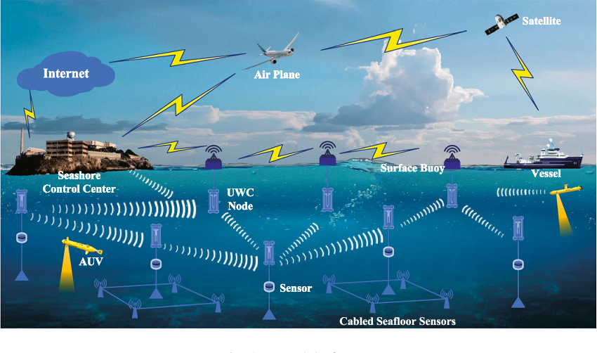
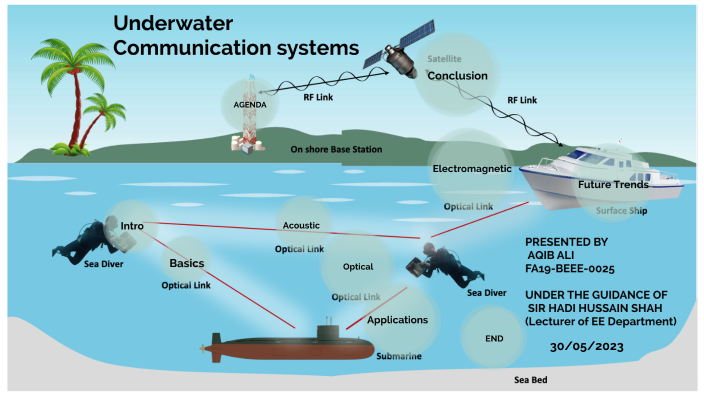
SVSEMBEDDED 9491535690 7842358459 underwater wireless communication Circuit Diagram Actually the low frequency is only used one direction, shore to the sub. And then it is on a prearranged schedule because the sub has to reel out miles of insulated wire antenna. To communicate back to shore, the sub has to either surface or release a communication device to the surface to allow communication, and then reel it back in.

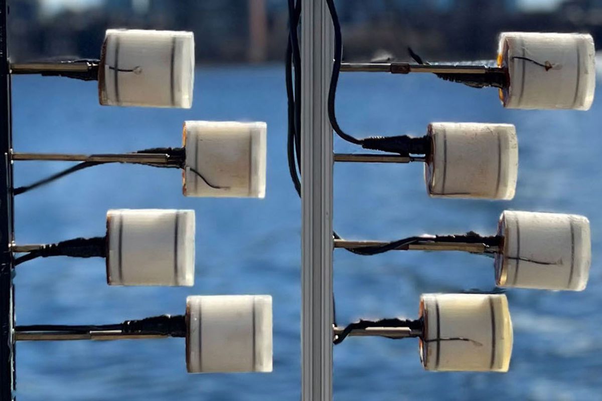
If in everyday life we use speakers (such as in your laptop or car) for sound emission and a microphone for sound recording, then I hurry to please you: sound transmitting underwater (we say "radiation") and sound recording are often performed by the same device, which is called an underwater acoustic (hydroacoustic) antenna, or hydrophone This guide teaches you how to connect the Ping Echosounder sonar with an Arduino to measure distances underwater. It can be used the make a basic fishfinder, boat depth sensor, and for ROV and robotics projects. 100 m range, 25 degree beamwidth, serial communication $ 460.00. Add to Cart. BLUART USB to TTL Serial and RS485 Adapter. With 0.1 Transmitter: The first Arduino (transmitter) reads the states of three slide switches.It creates a binary representation of the switch states and sends this data bit by bit using the IR LED. Receiver: The second Arduino (receiver) uses a photodiode to detect the IR light.It reads the incoming bits, reconstructs the data, and updates the states of the red, green, and yellow LEDs accordingly.

cost Hydrophone and Ultrasonic Transducer Circuit Diagram
Step 1.1: Choose a connection option and test the sensor on a short cable. Choose one of the following communication protocols: SPI (Serial Peripheral Interface) or an I2C (Inter-Integrated Circuit, aka I 2 C and IIC). I2C is recommended here because it is rated to go longer distances, uses fewer wires, and can be easily connected to this board with the STEMMA-QT 4-pin cable and connector. We use two water barrels in order to demonstrate underwater communication using ir signals passing through those containers. The system also has an acknowledgement receipt message that is sent back from the receiving circuit to the transmitting circuit on message receipt. This allows for efficient communication between two circuits wirelessly.

In this section, we'll guide you through the process of creating your own LED lighting system using cost-effective and bright 1W LEDs. With these steps, you can illuminate the underwater world and enhance your ROV's capabilities without breaking the bank. Building the LED Lighting System: Soldering the LEDs Build an Underwater Robot: Sea Perch is an innovative underwater robot. Building an under water robot is very cool. Of course, it takes lot of time. and make sure you can tell the difference between a "short" circuit (~0 ohms - touch the probes together) and an "open" circuit ("infinite" resistance - probes not touching). Some meters
