SensoDaily Smooth Dimming Touch Sensor LED Dimmer Switch for 12V DC Circuit Diagram a Touch Dimmer Switch using Arduino. The Touch Dimmer Switch Circuit is implemented using a Touch Sensor. This sensors are activated with the touch of human skin or a stylus holding an electrical charge. Fig -2: Touch Sensor 1.3 Aurdino In default the Arduino is not equipped with a display to visualize measuring-data, for example from your The size and shape of the touch-sensitive area depend on your lamp design and personal preferences. When designing the touch-sensitive area, consider the following factors: Size: The touch-sensitive area should be large enough to accommodate a human finger comfortably. A diameter of around 1 inch (25 mm) is usually sufficient. How to Design Touch Dimmer Switch Circuit ? The design of the Touch Dimmer Switch Circuit is very simple and is explained here. The touch sensor is given the power supply by connecting 5V to VCC and ground to GND pins. The SIG pin of the touch sensor is connected to any of the digital input / output pin of the Arduino UNO board.

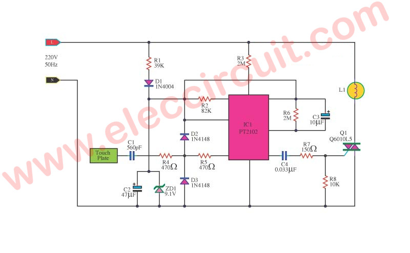
Figure 1. Phase control waveform for an AC mains voltage dimmer. Image source: LEDnique.com. Your LED circuit is low voltage, requires DC current and therefore will not work with this circuit. Don't be tempted to supply the 12 V power supply from a dimmer such as this. It won't like it. See the linked article for more information. At the third touch, the bulb is driven fully. Another touch puts off the light. The touch dimmer is built around 8-pin CMOS IC TT8486A/TT6061A specifically manufactured for touch dimmer switches applications. Since the IC is highly sensitive, use a long wire to connect the IC to the touch sensor. The circuit uses minimum external components. Now, if you touch the touch plate, the bulb glows dimly. On second touch, the bulb gives medium light. At the third touch, the bulb is driven fully and another touch puts off the light. This sensitive touch light dimmer circuit uses minimum external components and can be used for 110V or 220V AC by simply changing some external components .

Touch Dimmer Switch Project Circuit Circuit Diagram
A simple touch dimmer circuit diagram using TT6061 IC, which is a touch control integrated circuit used for Light dimmer circuit and lamp dimmer circuits. Home; DIY Motion Sensor Light using LED Bulb and PIR Sensor. March 8, 2017. PWM lamp dimmer using NE555. January 22, 2014. LED driver IC. December 22, 2011. 4 Comments
Touch Lamp Control Dimmer. HHere'sanother simple project where you use a touch sensor to control the brightness of your lamp, not just turn the light on/off. Also, we'll use an Arduino to design this circuit. Take a look at the circuit diagram below: Components Needed. Here are the components you need for this circuit: Breadboard (1) Touch

Touch Dimmer Switch Circuit using Arduino Circuit Diagram
(In the following images, a 220 Ω resistor is shown. But it could be a good idea to use a larger value like a 470 Ω resistor to make sure your LED can handle the current.) Step 3: Place The LED And Touchpad. Now, you're going to connect the LED and the touch-sensing part. For the touch-sensing part, you'll need two exposed wires. Now let us assemble all the components and make a switching circuit. A touch sensor is a touch-sensitive module which has 3 input/output pins. Power up this module by connecting the Vcc pin and ground pin to the 5V and ground of the Arduino. Connect the SIG or OUT pin of this module to the pin8 of the Arduino.