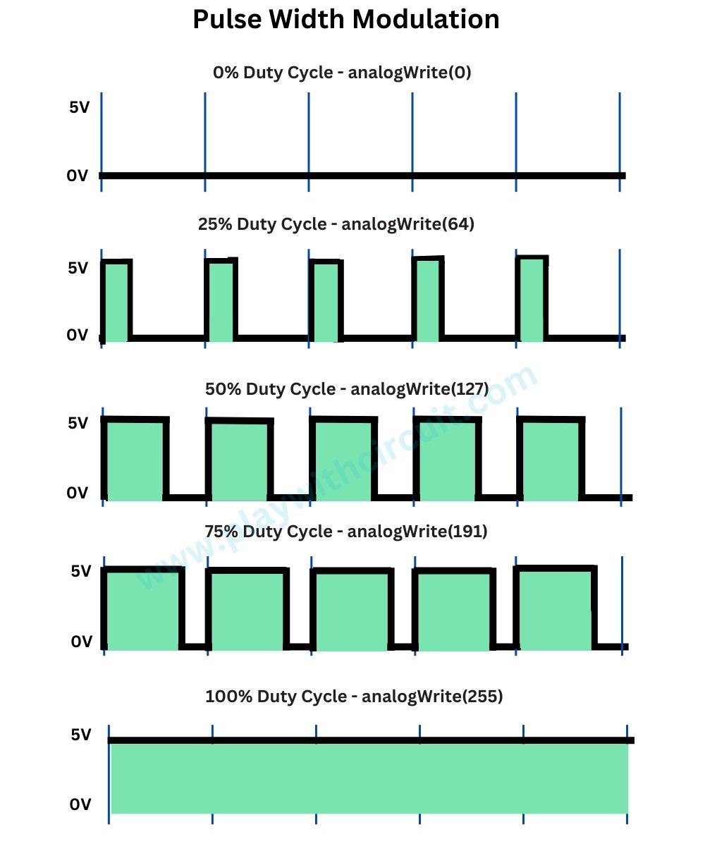
How to Use Pulse Width Modulation on the Arduino Circuit Diagram Pulse width modulation (PWM) is an essential skill for makers, hobbyists, and engineers alike. It allows microcontrollers like Arduino to control power delivered to electrical loads in an analog fashion using digital pins. In this in-depth guide, we will start from the basics - understanding what PWM signals are, how PWM works, and how it […] Pulse Width Modulation (PWM) is a technique used in electronics to control the amount of power delivered to a device by varying the width of the pulses in a digital signal. In simpler terms, PWM allows you to control the "average" voltage or power supplied to a device by turning the signal on and off at a rapid pace.
Pulse-width modulation (PWM) can be implemented on the Arduino in several ways. This tutorial explains simple PWM techniques, as well as how to use the PWM registers directly for more control over the duty cycle and frequency. This tutorial focuses on the Arduino Diecimila and Duemilanove models, which use the ATmega168 or ATmega328. Goals
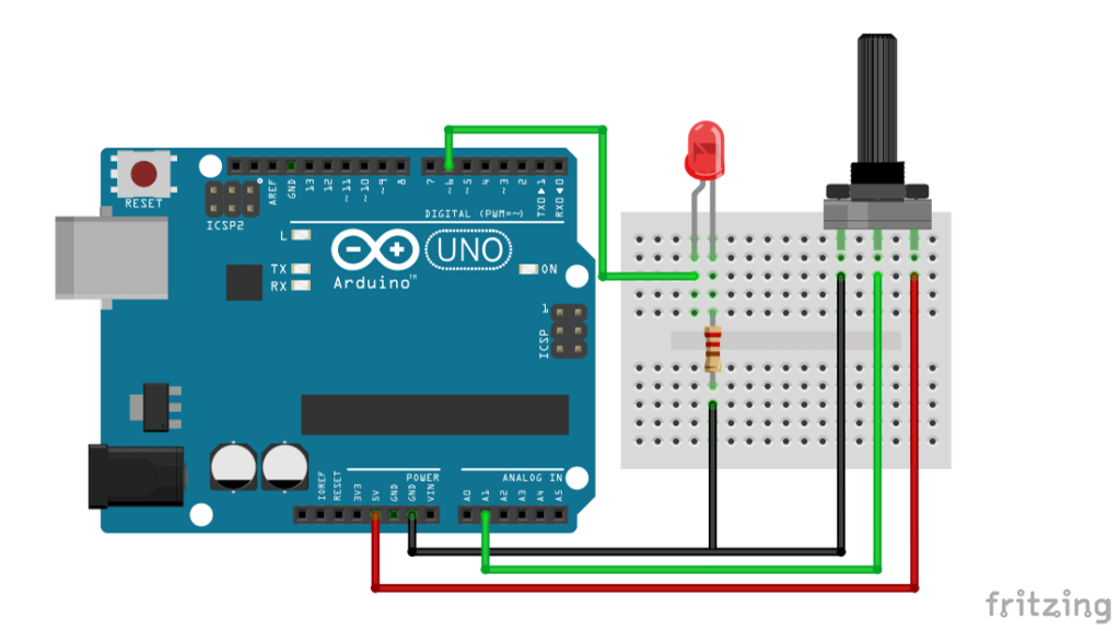
How to Use Pulse Width Modulation on the Arduino Circuit Diagram
In this tutorial, we will learn about Pulse Width Modulation (PWM) using an Arduino controller. Pulse Width Modulation, a crucial technique in electronics, allows us to generate variable-width pulses to represent analog input signal amplitudes. We will explore how the analogWrite() function in the Arduino IDE facilitates PWM generation. But before we dive into the
In this tutorial we will show different application examples of PWM(Pulse Width Modulation) using Arduino Nano.First we explain briefly about PWM, then explain how to generate PWM signal with Arduino Nano. Afterwards we show different application example of PWM which includes controlling brightness of a LED with software alone and using Potentiometer, control of motor and sound generation.

How to Use Pulse Width Modulation (PWM) on the Arduino Circuit Diagram
Pulse width modulation PWM: PWM stands for pulse width modulation which consists of a square wave with the help of which we can control the up or high time. It is simple but digital way to control the digital signals that we use to vary the energy that is send to a load or to encode information within the signal.
