end SMT Reflow Soldering Oven E10Top Lead Circuit Diagram On the other hand, industrial reflow machines are designed for mass production and can effectively solder a wider variety of components. Wave Soldering vs Reflow Soldering. Wave soldering and reflow soldering are complementary soldering techniques. In the chart below, you will find their main differences:

And wave soldering equipment is more affordable than reflow ovens. Wave Soldering vs. Reflow Soldering: Applications. Wave soldering is ideal for welding through-hole components on circuit boards, while reflow works best for surface mount components. Wrap Up. As you can see, wave and reflow soldering differ immediately from the start.
Reflow Soldering vs Wave Soldering: What's the Difference? Circuit Diagram
Reflow soldering, on the other hand, is better suited for SMD-heavy assemblies, providing precise and consistent solder joints with minimal thermal stress on components. When choosing between wave soldering and reflow soldering, consider factors such as component types, production volume, PCB complexity, budget, equipment, and quality requirements.

Also, you can always manually solder or hand solder PCB components, but this will rarely be a good approach if you have access to one of the mechanical methods of soldering. Manual soldering would only be an alternative to reflow soldering, but reflow soldering is still far superior. More on Soldering and Printed Circuit Boards
Wave Soldering vs. Reflow Soldering: What Are The Differences Circuit Diagram
Commercially there are two main soldering methods - reflow and wave. "Manual" soldering may still be used to add selected mechanically complex or large parts but this would be rare. "Manual" soldering could include the use of "robots" for the excessively keen. Wave soldering involves literally passing a wave of molten solder along a carefully

This video shows three different ways we solder electronic components to printed circuit boards: reflow, wave solder, and hand soldering.
A Comparison of Reflow Soldering and Wave Soldering Circuit Diagram
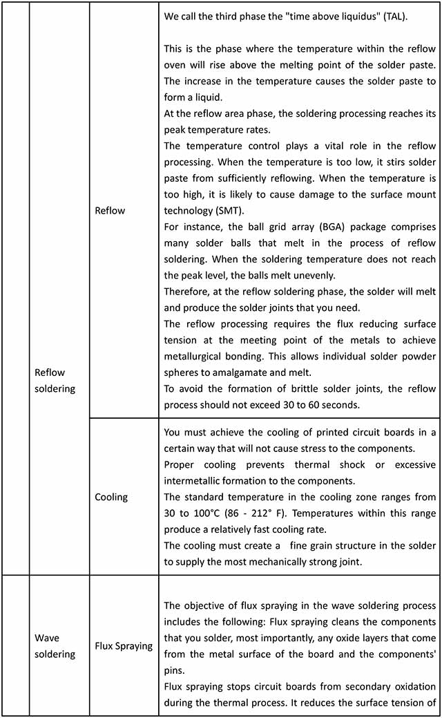
Unless you are soldering through-hole elements, reflow soldering is the most common method for many manufacturers (especially suitable for SMT assembly). Figure 1. The process of reflow soldering. The reflow solder process begins by applying flux and solder (also known as solder paste) to the pads. Hand soldering and robotic soldering are used for through hole components while wave soldering and reflow soldering are used for surface mount components. Robotic soldering is now being used to replace the time-consuming hand soldering. Reflow soldering is the commonly used technology for surface mount components which also uses wave soldering.

It is a well-known fact that hand soldering is a much less controlled process than the SMT process. If it handled correctly, hand soldering could introduce some quality issues. Here are some tips for hand soldering: The solder iron needs to be kept clean. The black crud built up from metal oxide and charred flux should be removed frequently.
