Capacitor for Audio Applications Circuit Diagram In many audio applications such as analog filter design, the preferred solution is to use C0G/NP0 ceramic capacitors because they have much better performance and are still available in small packages. While this is a great solution, it is not always feasible. In audio signal chains, keeping resistances low minimizes noise, The most useful filters with ease of use and best all-around performance are the Sallen Key active filters. Sallen Key filters are two-pole filters, meaning they have two reactive components (capacitors). All of the circuits below are based on this design. Low Pass Filter. In a low pass filter, frequencies above a certain point are blocked:
A filter is a device that passes electric signals at certain frequencies or frequency ranges while preventing the passage of others. — Webster. Filter circuits are used in a wide variety of applications. In the field of telecommunication, band-pass filters are used in the audio frequency range (0 kHz to 20 kHz) for modems and speech processing.

beavis audio research Circuit Diagram
Variable Low-Pass Filter. Here we use a small value cap (500pf up to 50nf is a good range for experimentation) wired in the signal path of a circuit. If the pot's wiper is at the full open position (no resistance) the signal will bypass the cap and go straight through. learn more about filter design. 1.1 Filters and Signals: What Does a Filter Do? In circuit theory, a filter is an electrical network that alters the amplitude and/or phase characteristics of a signal with re-spect to frequency. Ideally, a filter will not add new frequen-cies to the input signal, nor will it change the component frequencies of Next, high pass filter is designed to attenuate frequencies from 0 to 9.75 kHz. Cut-off frequency is set to 9.75 kHz and standard capacitor value for audio circuit design chosen to be 0.01 micro Farads. To calculate Resistor values for High pass filter Equation 2 is used. Where: m = magnitude coefficient f c = 9.75 kHz Cs = 0.01 micro Farads D
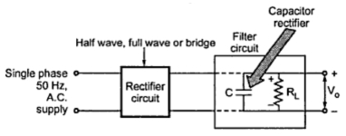
This helps ensure that the audio signal is of the highest possible quality. The most common type of noise filter circuit is a passive low-pass filter. This uses inductors and capacitors to block higher frequency signals and allow lower frequencies to pass. Other types of filter circuits include high-pass filters, notch filters and bandpass The low pass filter circuit which is the prime part of this project, filters a frequency spectrum or any mix of frequencies. The frequencies above the cut-off frequency of the circuit are bypassed to the ground by the capacitor C. This is a capacitive low pass filter which has a resistor connected in series and a capacitor in parallel with the output. For example, hi-fi audio goes down to 20 Hz. For some headroom, it's a good idea to design your circuits with high pass filter rolloffs at 10 Hz or so. The impedance magnitude of a capacitor is 1 / 2πfC, with f in Hz, C in Farads, and the result in Ohms.